IKW
Induction kinetic welding (IKW): An innovative one-shot solid-state technique for circular joints
Authors: Farzad Khodabakhshi, Mark Turezki, Adrian P. Gerlich
Affiliation: Department of Mechanical and Mechatronics Engineering, University of Waterloo, Waterloo, ON, Canada
Research paper was accepted and published by Elsevier.
Highlights
• Induction kinetic welding (IKW) concept introduced as a novel solid-state joining technology
• Solid-state microstructures of the IKW bond are characterized for the first time in any material
• Critical welding processing parameters were optimized as the peak temperature of 1400°C and tangential rotation of up to 60-deg
• A joining efficiency of up to 100% achieved with base metal fracture in the tube section
Abstract
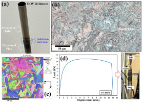
In this research, an innovative solid-state joining technology has been introduced for butt-welding of circular sections with dissimilar tube and rod geometries, using induction kinetic welding (IKW). This process involves using induction to preheat material before bringing the pieces together, where rapid heating to below the base metal melting temperature followed quickly by applying axial force and shear rotation at the joint interface. A homogeneous weld microstructure consisting of refined grains and minimal heat affected zone (HAZ) is formed at the contact interface. The present work demonstrates this for a specific application involving a circular plug (with a diameter of ∼13 mm) and thin-walled tube (with a diameter of ∼13.4 mm and a wall thickness of ∼0.35 mm) both consisting of Zircaloy-4. Among the IKW processing parameters, the influence of preheating temperature and rotational shear displacement angle are the most critical inputs examined. The final joint stress distribution near the peak fracture load was modelled using finite element analysis (FEA). To this end, induction heating up to the temperature of ∼1400°C followed by a frictional shear-rotation angle of 60-degrees achieved formation of a sound solid-state weld with upset and removal of oxides from the contact interface. Afterward, the microstructural characteristics across the welding line and mechanical properties of the produced weldments were examined. A joining efficiency of 100% was achieved during the tensile fracture of the tube/plug weldment where fracture of the tube base metal has been achieved.
Graphical abstract
Keywords
Solid-state joining, IKW, Zircaloy-4, Microstructure, Mechanical properties
Introduction
In the past decades, several welding technologies including arc welding, laser welding, flash welding, upset welding, induction welding, and friction welding have been developed to increase productivity and integrity demanded by a wide range of industries (David and DebRoy, 1992; Welding Handbook Ninth Edition Volume 2: Welding Processes, Part 1; Welding Handbook Ninth Edition Volume 2: Welding Processes, Part 2). The use of ‘one shot’ welding processes offers the potential to achieve both, where various heating and force applications methods can be automated to promote joining in both solid state and fusion welding mechanisms (Yapp and Blackman, 2004). Flash butt-welding was one of the primary joining technologies that have been demonstrated for onshore weld-engineering applications resulting in the weldments with quick processing times and high integrity (Welding Handbook Ninth Edition Volume 1: Welding Science and Technology; Fujii et al., 2015). However, in the case of scaling up to large diameters, high levels of current and voltage would be required to rapidly melt the contacting/flying surfaces (Li et al., 2013; Oladimeji et al., 2016). Upon flash butt-welding, the edges will be subjected to localized melting, and then under the upsetting/forging pressure, the molten hot metal is expelled out during joining process to yield flash formation while one workpiece is fixed (Li et al., 2013; Oladimeji et al., 2016; Wang et al., 2005). Localized surface melting and upset flash formation leads to a sharp weld line, alongside oxides and other inclusions with could be moved out from the nugget zone and squeezed in the flash portion (Lippold, 2014). Trimming off the flash from the upset joint provides a smooth weldment without any potential region for stress concentration (ASM Handbook Volume 6: Welding Brazing and Soldering). This procedure has been used in production of shafts, rods, strips, and wires from different metals and alloys in industrial use (Çetinkaya and Arabaci, 2006; Lu et al., 2017; Ma et al., 2015; Zhang et al., 2007).
An alternative procedure involves upset resistance welding (URW), and high-frequency upset welding (HFUW), using the same principles for joining, however by applying heat through electrical resistance (instead of electric flash) at the interface to promote localized melting followed by upsetting to create the joint-line (Welding Handbook Ninth Edition Volume 2: Welding Processes, Part 1; Welding Handbook Ninth Edition Volume 2: Welding Processes, Part 2). For this technique, two workpieces are put in contact before applying the current through holders at a specified distance from the interface (Kerstens and Richardson, 2009, Le Gloannec et al., 2016). High frequency upset resistance seam welding can also be achieved using high-frequency current at the edges of longitudinal pipe welds during a production mill (Welding Handbook Ninth Edition Volume 1: Welding Science and Technology). In all of these welding techniques, filler metal is not utilized, and the forging pressure and time during upsetting are critical aspects for the solid weld formation (ASM Handbook Volume 6: Welding Brazing and Soldering; Andreoli et al., 2018; Sharifitabar and Halvaee, 2010).
Induction welding is another one-shot welding process resembling the above technologies, but with a different heating method (Welding Handbook Ninth Edition Volume 2: Welding Processes, Part 1; Welding Handbook Ninth Edition Volume 2: Welding Processes, Part 2). In this process, the edges can be heated up to the melting temperature by a non-contacting induction coil and applying the high-frequency current, while the heating uniformity around the edges is usually influenced by the skin effect (Welding Handbook Ninth Edition Volume 1: Welding Science and Technology). Moreover, the alignment of the pipes while applying the center-line axial forging force may be challenging, along with achieving uniform pressure across the joint area (Kang et al., 2020; Yan et al., 2011). The upsetting step is essential to the formation of a sound joint with satisfactory properties, requiring careful control of the pressure and time (Kang et al., 2020; Yan et al., 2011). The applications for induction welding techniques are similar to flash welding and upset resistance welding, but with a more controlled heating stage (Sun et al., 2014; Zhang et al., 2015).
Concerning the previously described fusion-based welding technologies for joining tubular in various industries, conventional rotary friction welding can compete as a solid-state welding technology with high-volume production capacity and potentially superior properties by maintaining materials in the solid state by friction heating and mechanical deformation bonding (Li et al., 2013; Lippold, 2014; Li et al., 2016; Mallieswaran et al.). This welding process requires rotational motion of two components in contact to generate heat and deformation at the interface at hundreds of RPM (Welding Handbook Ninth Edition Volume 2: Welding Processes, Part 2). Usually, one part is fixed, and the other one rotates at a specific speed against the fixed counterpart under an axial pressure (Bhamji et al., 2011). The required energy kinetics for operation of such the friction welding methodology can be provided under two schemes of inertia and direct drive variations (Welding Handbook Ninth Edition Volume 1: Welding Science and Technology; Bhamji et al., 2011). After generating the frictional heat and plasticizing the edges of components, the rotation process can stop, and the solid-state weldment forms while a forging force is applied (Li et al., 2010). In this friction welding process, there is no need to use any shielding gas, flux cleaning, or even filler metal. The formation of oxides along the interface upon heating is suppressed by the outward extrusion flow from the edges during the final forging upset displacement (McAndrew et al., 2018; Turner et al., 2011). Although rotary friction welding process has been widely used for butt-joining of circular solid rods, welding of dissimilar shape, or tubular parts particularly with thin sections poses some challenges, because sufficient force cannot be applied to achieve the necessary heat and pressure for bonding (ASM Handbook Volume 6: Welding Brazing and Soldering; Bhamji et al., 2011; Mohan and Gopi, 2018; Bhamji et al., 2010).
In this manuscript, an innovative solid-state joining technology is demonstrated based on combining the principles of induction welding and friction welding techniques. This process has been referred to as “induction kinetic welding (IKW)” or friction-assisted induction welding based on US Pat. US-2024-0101291-A1 (Cheng, 2017), and has only been reported once in a review by Yapp and Blackman (2004), though without any analysis of the joint properties. As such it presents great potential for controlling the weld flash and heat-affected regions around the weld line normally associated with other one-shot processes mentioned above (Cheng, 2017). Also, undesirable phase transformations and solidification-related defects could be suppressed at the bond-line and its surroundings due to the quick induction heating below the melting point and subsequent rapid cooling/quenching (Kou, 2002). More refined grain structure of weld nugget with superior mechanical properties would be expected based on the applied tangential friction-based shear plastic deformation at the interface. In this context, the localized tangential shear deformation by IKW after quick induction heating, mainly contact-friction assisted, can reduce the chance of typical bucking risks that usually could happen by conventional rotatory friction welding technology due to non-localized excessive heating and higher applied forging forces than IKW. As a concise comparison, this innovative IKW technology has a higher potential than the other solid-state joining techniques, like flash welding, rotary friction welding, and HFUW, in terms of energy efficiency, joint quality, and material suitability. In fact, IKW is something between two processes of conventional induction and rotary friction welding beyond the integration aspect, in that traditional induction welding does not apply significant shearing to the material, and traditional friction welding mainly relies on the deformation shearing for heat generation. As such, the microstructures are quite distinct due to the different contributions of induction and deformation heating. Hence, such IKW technology is entirely novel as an alternative solid-state joining method, and no prior studies of the material welded using this process are currently available.
As a case study of the IKW process, here we consider the solid-state welding of a thin walled Zircaloy-4 tube to a plug, examined as an alternative to the resistance upset welding process that is currently used in the application of fuel bundle assembly in the nuclear industry (Bi et al., 2024). As an initial application study, the welding process parameters were optimized for formation of similar Zircaloy-4 weldments with dissimilar geometry. The effects of peak heat-up temperature, normal applied pressure, and tangential rotation distance were established to be crucial aspects of this IKW technology and defect-free weldments with good quality of metallurgical bonds at the interface were examined. The processing conditions which produced satisfactory visual appearance were considered for further microstructural and mechanical studies. In addition to visual inspection, the thickness cross-sections were analyzed by optical microscopy (OM) and electron backscatter diffraction (EBSD) characterization. Afterward, the mechanical performance of the welds was evaluated by indentation hardness measurements, axial tensile testing, and fractography of tested joints. The main goal of the present study focuses on elaborating the potential and capability of the IKW technique for creating solid-state weldments with superior performance to other competing conventional technologies reviewed above. The only competing technology for the tube to plug joining has been resistance welding which has been referenced in the case of papers (Feng et al., 2022, Feng et al., 2023, Shafy et al., 1986). In each of these cases, the principle first requirement is to achieve bonding which exceeds the force required to fracture the tube material. Future testing of the IKW joints will involve other aspects such as pressure tests and corrosion or high temperature tests. Also, to this end, the solid-state joining of tubular materials using this welding technique may hold potential for other applications such as pipeline and transportation components.
Materials and experimental methodology
Induction kinetic welding (IKW) experiments
Raw materials
Welding involved using the Zircaloy-4 zirconium alloy material in two forms: solid rod and thin-wall tube. The chemical composition for both the rod and plug Zircaloy-4 parts are presented in Table 1, which was supplied by Cameco. In this case, the as-received tube had an outside diameter of ∼13 mm and a wall thickness of ∼0.35 mm. Also, the rod diameter was ∼13.4 mm. Before the joining experiments, the end diameter on the rod was machined to fit within the inner diameter of the tube by machining the corresponding diameter down to ∼11.8 mm for a length of ∼8 mm along one-end of the rod. Then, the joining of the tube to plug by a butt-joint design was performed by IKW technology using different processing parameters. This is worth expressing that the surfaces for both rod plug, and tube have been completely cleaned before welding process to minimize contamination, and the typical native oxide on the materials would have a thickness of < 1 µm (Platt et al., 2015).
Table 1. The assessed ranges of induction kinetics welding parameters for Zircaloy-4 tube to plug fit-joining design.
Elements | Zr | Cr | Fe | FeCr | O | Sn |
Amount | Balance | 0.10 wt.% | 0.30 wt.% | 0.30 wt.% | 1328 ppm | 1.30 wt.% |
Fabrication of weld joint components
The rod portion was machined to a plug shape with a groove feature similar in depth to the thickness of the tube wall. The welding environment was made inert using argon gas while heating was applied by an induction coil, controlled by a pyrometer focused on the end of the rod to provide closed loop temperature control. A supplementary video clip displaying the joining process and thermal measurements during the induction heating. This temperature measurement was made using a two-color pyrometer, which is an industry standard method for surface measurement that avoids the need to compensate for emissivity as in the case of most thermal cameras. The precise induction heating uniformity has been managed by placing the pyrometer precisely using a guide laser, and the thermal distribution is naturally promoted in a symmetrical shape radially due to the geometry of the cylindrical coil. For precise and uniform control of the induction heating, the pyrometer measured the point temperature of the outer diameter of the Zircaloy-4 rod, halfway into the depth of the coil. The pyrometer was situated 485 mm linearly away from the measurement point. The heated portion was moved out of the coil once the desired temperature was reached and contacted the tube within 0.75 seconds and pressed into the tube with a force that reaches a peak of 150 kg. This was followed by a rotation relative to the tube, a specific angle for each welding parameter. During this process, the tube is guided over the end of the rod such that it would be constrained and forged to the rod (Cheng, 2017). The samples were allowed to cool before removed from the apparatus.
The set of processing parameters assessed in this research by IKW technique are expressed in Table 2. As addressed in this table, the effects of processing parameters in terms of testing temperature involved preheating of the rod material to temperatures between 1000 to 1600°C within 5 seconds, applying the forging force followed by a tangential rotational from 30 to 60-degrees to achieve shear rotation and promote solid-state metallurgical joint formation. In this case, a wide range of these IKW joining parameters has been evaluated in advance to achieve evidence of bonding with good visual quality, as listed in Table 2, including temperature, forging force, angular velocity, and rotation distance. The reported values and ranges in Table 2 are only relevant to the parameters of joints characterized here in terms of weld formation. In this project, preheating temperatures ranging from 1000 to 1600°C, eventually led to formation of a sound solid-state weldment with the 100% joining efficiency.
Table 2. The assessed ranges of induction kinetics welding parameters for Zircaloy-4 tube to plug fit-joining design. In this table, Fmax is the highest level of applied normal force upon IKW butt-joining, θ is the turn angle clockwise, and ω is the corresponding rotational speed in degrees per second for tangential shear angular speed along the clockwise direction.
Test number | Outside diameter (mm) | Locator diameter (mm) | Locator length (mm) | Pipe stand-off (mm) | Temperature (°C) | Argon shielding time | Push velocity | Fmax (Kg) | θ | Ω |
G10-1 | 13.3 | 11.8 | 6 | 3 | 1000 | Upon heating | 150 | 100 | 60 | 1600 |
G10-2 | 13.3 | 11.8 | 6 | 3 | 1000 | Upon heating | 150 | 100 | 60 | 1600 |
G12-1 | 13.3 | 11.8 | 6 | 3 | 1200 | Upon heating | 150 | 100 | 60 | 1600 |
G12-2 | 13.3 | 11.8 | 6 | 3 | 1200 | Upon heating | 150 | 100 | 60 | 1600 |
G12-3 | 13.3 | 11.8 | 6 | 3 | 1200 | Upon heating | 150 | 100 | 60 | 1600 |
G14-1 | 13.3 | 11.8 | 6 | 3 | 1400 | Upon heating | 150 | 100 | 60 | 1600 |
G14-2 | 13.3 | 11.8 | 6 | 3 | 1400 | Upon heating | 150 | 100 | 60 | 1600 |
G14-3 | 13.3 | 11.8 | 6 | 3 | 1400 | Upon heating | 150 | 100 | 60 | 1600 |
G14-4 | 13.3 | 11.8 | 6 | 3 | 1400 | Upon heating | 150 | 100 | 60 | 1600 |
G14-5 | 13.3 | 11.8 | 6 | 3 | 1400 | Upon heating | 150 | 100 | 40 | 1600 |
G14-6 | 13.3 | 11.8 | 6 | 3 | 1400 | Upon heating | 150 | 100 | 60 | 1600 |
G14-7 | 13.3 | 11.8 | 6 | 3 | 1400 | Upon heating | 150 | 100 | 60 | 1600 |
G14-8 | 13.3 | 11.8 | 6 | 3 | 1400 | Upon heating | 150 | 100 | 60 | 1600 |
G14-9 | 13.3 | 11.8 | 6 | 3 | 1400 | Upon heating | 150 | 100 | 60 | 1600 |
G16-1 | 13.3 | 11.8 | 6 | 3 | 1600 | Upon heating | 150 | 100 | 60 | 1600 |
G16-2 | 13.3 | 11.8 | 6 | 3 | 1600 | Upon heating | 150 | 100 | 60 | 1600 |
G16-3 | 13.3 | 11.8 | 6 | 3 | 1600 | Upon heating | 150 | 100 | 60 | 1600 |
Some critical challenges for successful IKW processing can be described as follows. The concentricity should be maintained during joining, without warping or deflection. The end of the rod away from the joint remains cool, which inhibits deflection along the remaining workpiece. Also, the plug/locator helps maintain concentricity based on the close tolerance of the machined smaller diameter of the rod and the tube. Also, purging the atmosphere using argon gas was monitored to minimize the chance of oxide formation, that makes the joining process feasible. Without effective argon gas shielding, it was not possible to promote metallurgical bonding. In the supplementary video, the IKW technology for solid-state joining of Zircaloy-4 plug to tube design is shown for reference. Also, the image from one of the Zircaloy weldments is shown in Fig. 1.
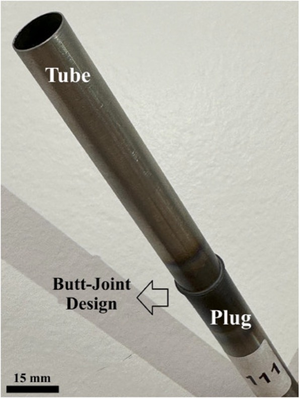
Fig. 1. Weldment by IKW technology between a plug and thin-walled tube of Zircaloy-4.
Microstructural studies of joint designs
For the purpose of microstructural characterization of the produced weldments under different IKW processing parameters, cross-sectioning was carried out by cutting half-way through the selected samples using a water-jet machine. Thereafter, the cross-sections were mounted and prepared via standard metallographic methods. These include typical grinding and polishing steps, such that the grain structure of different regions across the weldment and the resulted bond-line was revealed using the electrochemical etching procedure. This was done by applying the chemical reagent made of perchloric acid and methanol with the ration of 10:1, applying a voltage of 12 V, a current of 0.8 A, for a holding time of up to 30 seconds. Then, the microstructure of electrochemically etched specimens was studied under a ZIESS optical microscope (OM). Also, further microstructural and textural investigations were conducted on the weldments using electron backscatter diffraction (EBSD) analysis. Regarding the preparation of EBSD samples, the finalized OM specimens before chemical etching were subjected to vibratory polishing with 0.05 µm colloidal silica (OPS suspension), up to 12-hours, followed by the broad-angle ion-milling for up to 2-3 hours, resulting in satisfactory index rate of >90%. The EBSD measurements were performed using a raster pattern of 625 × 625 and with a step size of 0.4 µm.
Mechanical properties by indentation and tensile testing
To assess the mechanical properties of the weld joints, microhardness indentation testing and tensile loading up to the fracture point were utilized. V-grooved grips were used to secure the tube end and rod end in the machine, with testing conducted at room temperature. The tensile tests were performed at a constant loading rate of 1 mm/min using a 100 kN capacity MTS machine to failure. The reported tensile behaviors in this research have been repeated at least five times per each processing state, and the resulting averages are reported. In this case, depending on the number of measurements, the corresponding standard deviations for the reported mean value were calculated. The corresponding facture locations for the longitudinal tensile failed specimens were analyzed by visual examination and microscopy. To this end, the tensile flow curves from the loaded specimens up to rupture were analyzed and reported in addition to the corresponding fractured weldments. In addition to tensile testing for estimating the joining efficiency of weldments, Vickers indentation testing across the optimized weld joint was performed to measure the micro-hardness profiles around the produced tangential bond-line concerning the primary tube and rod base alloys. Measurements were performed using Vickers indenter with a 200 g load, and after covering the regions around the cross-section of IKW circular weldment, the hardness results were plotted using MATLAB software.
Modelling of Zircaloy-4 tube to plug fit-in solid-state butt-joining
For the purpose of evaluating the stress distribution in the completed joint, modelling of the static stress distribution during tensile testing was performed by finite element analysis (FEA), based on the actual joint cross-section that was produced, which was used to generate the axisymmetric geometry in Solidworks by tracing the joint profile. This cross section was extruded into a 3D model as shown in Fig. 2, on which the FEA simulations were run. The sample was cut short on either side to reduce the size of the mesh, and in turn reduce processing time, with the same fixed boundary condition of the static grip and load applied to the tube section. Since the area of interest is the joint and immediate area surrounding it, removing the excess material from the simulation is an acceptable simplification. Afterward, the von Mises stress distribution profiles regarding the produced weldment across the different sections of the plug into tube butt-joint were estimated and demonstrated. These FE simulations used the identical geometry, loading state, and boundary conditions, of the welds which were mechanically tested, along with the stiffness and yield stress of the Zircaloy-4 material provided. In the case of the simulation, the purpose is to show that the at the maximum fracture load, the highest stresses away from the joint interface, which is to help explain why base metal fracture occurs in the tube as observed in the experimental tests.
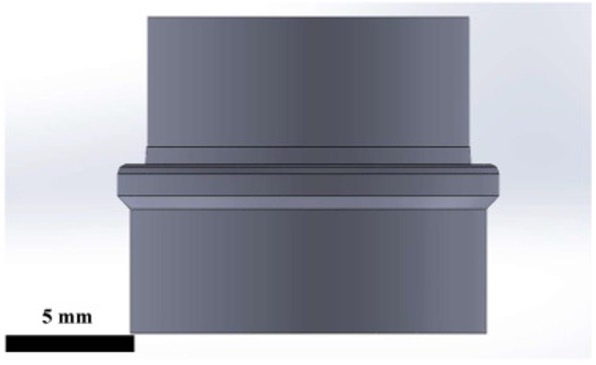
Fig. 2. The design model was utilized for simulation of plug into the tube butt-welding
Results and discussion
Micro-profiles of cross-sections for the tube/plug joint design formation
In Fig. 3, the macro-profiles using low-magnification microscopy are given for the right- and left-sides of the created solid-state weldment between tube and plug across its thickness cross-section, along with the corresponding ligament areas. Complete metallurgical bonding between the edge of tube and groove on the plug under the butt-joint design can be observed. Also, the formation of two flash regions of extruded material is found on both sides, which signifies the radial upsetting of the solidified materials due to the friction-assisted tangential rotation of tube against plug under preserved forging pressure after induction heating. Furthermore, as indicated by blue-boxes on Fig. 3, the microstructure of welded regions and their surroundings seem different than the primary Zircaloy microstructures observed in either the tube or plug, which requires further identification by high-magnification microscopy as follows.
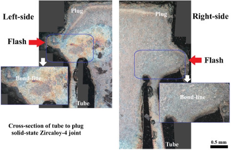
Fig. 3. The macro-profiles for the thickness cross-sections of the tube to plug butt-weldment prepared using the processing conditions defined by G14, demonstrating the left and right-sides macrostructure of bond-line formation.
Microstructure of welded regions by optical microscopy and EBSD analyses
Fig. 4 illustrates the optical microstructures for different locations of the primary rod made of Zircaloy-4 across its thickness section. The microstructure of plug seems entirely homogeneous at various regions and consists of elongated transformed β-phase structure, due to the hot-rolling process implemented in production (Aranas et al., 2018), which randomly oriented along different directions in packets that are approximately 20 to 50 µm in diameter. This Fig. 4 displays the microstructure of the primary Zircaloy rod from different regions through the thickness, indicating negligible differences from the production processing. Meanwhile, as demonstrated in Fig. 5, the microstructure of the Zircaloy-4 tube in its as-received state was completely different than that of the rod material. The primary microstructure of tube base alloy includes the relaxed α-phase with an almost equiaxed morphology, that probably formed by equilibrium cooling upon manufacturing process (Pshenichnikov et al., 2015). However, in the case of Zircaloy-4, considering the microstructural profiles of Fig. 3, these primary microstructures were considerably affected in the weldment regions by the IKW solid-state joining technique.
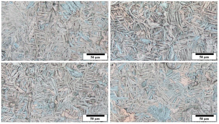
Fig. 4. Optical microscopy images showing the grain structure of primary rod Zircaloy material utilized as the plug-design.
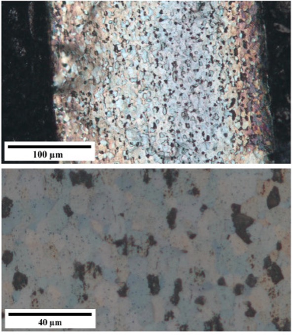
Fig. 5. The grain structure of the as-received tube.
Fig. 6 displays the optical microstructures from the bond-line between the tube and the plug made by IKW technology. As illustrated, except for the right-side edge of the joint-line which pushed out toward the flash by upsetting and can be machined-off afterwards, the metallurgical bond has formed across both sides of the diameter. The primary interface between counterparts had entirely disappeared after solid-state joining, particularly away from the edges of bond-line. Regarding the primary existing zirconium oxide layer on the surface of components and those with the chance of formation upon induction heating despite the argon-gas shielding effect, they were pushed outside of the joint interface by upsetting during the friction-assisted tangential rotation, leading to the formation of a circular flash around the weldment as the related left- and right-side thickness sections are presented in Figs. 7a and 7b, respectively.
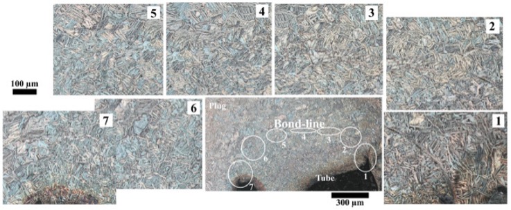
Fig. 6. Optical microstructures for the joint line across the solid-state bonded tube to plug geometrical designs
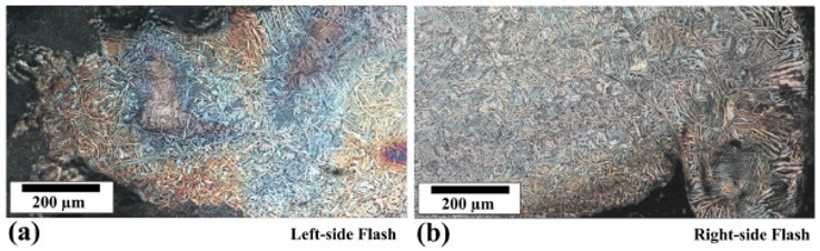
Fig. 7. Optical micrographs for the generated flash material around the produced weldment: (a) Left-, and (b) right-side flashes.
The microstructure of different locations in the heat affected zones (HAZ) around the produced solid-state weldment by optical microscopy imaging are depicted in Fig. 8, combined with the macro-profile of joints between tube and plug. As shown for eleven locations in this figure around the produced weldment, the microstructure of all HAZ regions retains an acicular lath structure, with some differences in structure between the rod and tube. The structure of all locations for the HAZ region appears to be a β-phase structure based on the EBSD indexing, similar to the bond-line, while the size of the lath structure and its needles varies based on location around the HAZ indicated with points one to eleven in Fig. 8, depending on the applied shear plastic strain and subsequent cooling action during and after IKW processing of the tube to plug joint due to a heat-sinking effect (Lippold, 2014). As shown, in the locations 3, 4, 5, and 8, toward the bottom part of the joint design, caused by likely a higher degree of plastic deformation and higher cooling rates, such that the needle-like β-phase structure of these regions seem finer than the other top and middle parts of the HAZ area.
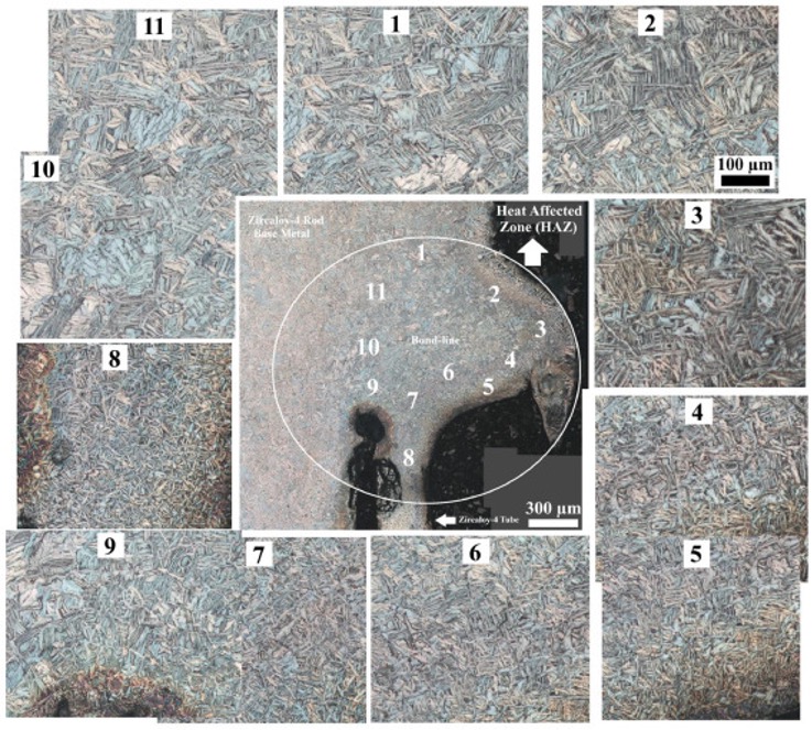
Fig. 8. Grain structures of heat affected regions near to the bond-line after solid-state joining by IKW technology.
Fig. 9, Fig. 10 represent the EBSD microstructural maps and textural data plots for the joint line of the solid-state weldment from its right- and left-sides cross-sections. Consistent with optical microscopy microstructures, complete metallurgical bonding at the tube and plug interface after solid-state joining is revealed. Also, different grain boundaries, inverse pole-figure (IPF), and band contrast microstructural maps in Figs. 9a-c and Figs. 10a-c suggest the formation of a random elongated structure of β-phase needles for the weld region. The phase-color maps revealed by EBSD analysis in Figs. 9d and 10d from the right- and left-sides of the weld confirm negligible oxidation considering no Zr oxides were indexed at the solid-state weld-line. As discussed before, some slight surface oxidations can occur during IKW processing despite the use of argon gas shielding, due to high reactivity of zirconium. Meanwhile, since the thickness of such a trace oxide layer would be under a micron, it will be broken by tangential shear deformation upon IKW bonding, which could lead to dispersal of the continuous oxides at some point along the interface of the parts and pushing them outside of the joining region. Hence, these phase analyses by EBSD characterization from the joint interface can confirm the oxides displacement and removal from the joint interface. Also, based on the EBSD pole-figures of Figs. 9e and 10e, generation of very strong Goss- and β-phase textural components after IKW joining Zircaloy-4 can be identified, that could be induced by induction heating and consequent friction-assisted tangential rotation upsetting (Lecomte and Bunge, 2015, Girard et al., 2001, Guo et al., 2021, Liu et al., 2018). Such textural evolutions can correlate and control the subsequent mechanical performance of produced weldments.
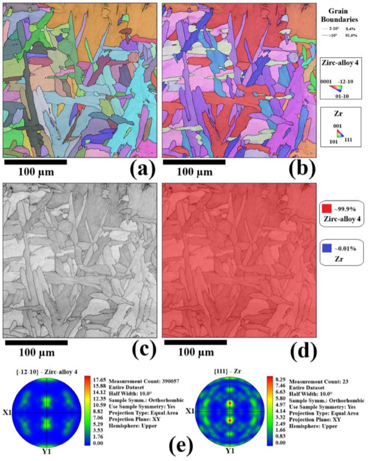
Fig. 9. The EBSD microstructural characterization results from the prepared weldment for the right-side weld-line: (a) Grain boundary map, (b) inverse pole-figure grain structure, (c) band contrast microstructure, (d) phase-color map, and (e) pole-figure textural plots regarding the <-12-10> Zircaloy-4 and <111> zirconium projections.
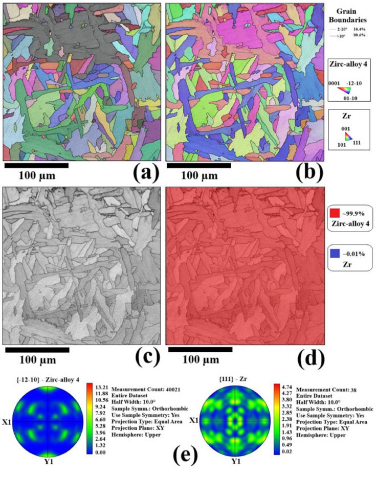
Fig. 10. The same EBSD analysis information as Fig. 9 for the weld-line from the left-side of prepared IKW circular weldment: (a) Boundary, (b) IPF microstructure, (c) band-contrast of grains, and (d) phase maps, as combined with (e) the corresponding PF textural orientations.
This is worth noting that the rapid cooling after forging by material heat-sinking and argon gas shielding effects could contribute to the grain structure of weld, resulting in the formation of the interesting refined microstructures along the weld line, as characterized by EBSD analysis in Fig. 9, Fig. 10. Also, this is expected that residual stress could be also affected by rapid cooling after forging, which this matter will be assessed in future studies.
Joining efficiency and fracture behav
ior of produced weldments
The reported values and ranges in Table 2 refer to the parameters which result in the formation of suitable weldments which may achieve base metal fracture in the tube. In this project, temperatures were set to be a target from 1000 to 1600°C, since no prior data was reported for this process, and 1400°C which corresponds to the G14 samples was found to be the first to achieve best joining efficiency.
Based on the tensile loading experiments of the fabricated Zircaloy-4 weldments between tube and plug at different testing temperatures, all joints prepared at lower temperatures of 1000 (G10) and 1200°C (G12) failed at the weld faying interface region. However, the weldments with higher testing temperatures of 1400 (G14) and 1600°C (G16) displayed more satisfactory results, as presented in Fig. 11, Fig. 12, respectively. The produced joints with a preheat of 1400°C provided the best repeatability in strength, as shown in Fig. 11, where they all fractured from the tube base metal and accordingly reached a peak load of 10.8 kN. Meanwhile, in the case of welds processed at higher temperatures of 1600°C, corresponding to specimen G16 as depicted in Fig. 12, despite higher fracture loads compared to the G10 and G12 specimens, most fractured from the weld line. Such tensile flow properties and corresponding fracture behaviors suggest G14 conditions are superior, with a joining efficiency of up to 100%, which can guarantee the failure of tube to plug weldments from tube Zircaloy as the weakest base material.
.jpg)
Fig. 11. Tensile flow curve for the produced tube/plug weldment with fractured appearance of the specimen joined at a temperature of 1400°C indicating base metal fracture in the tube.
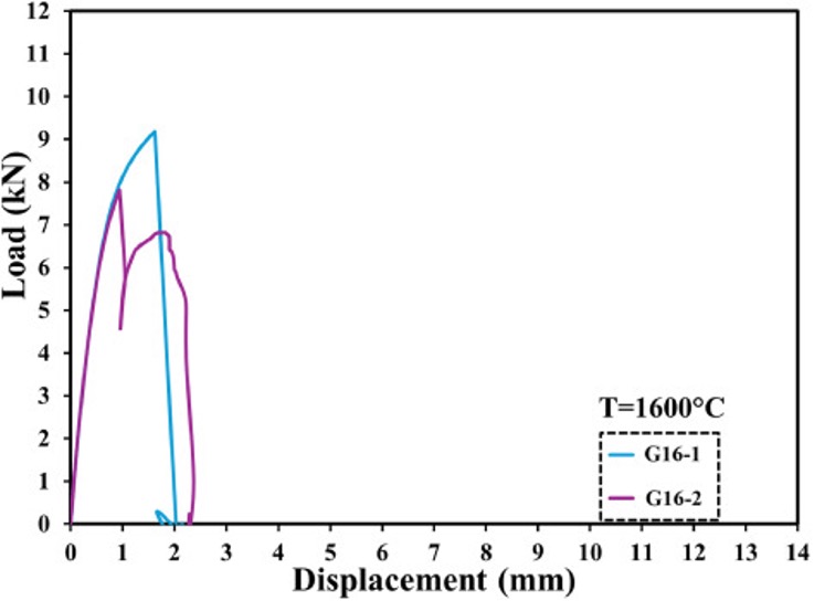
Fig. 12. Tensile flow behaviors up to the rupture state for the prepared weldments with 1600°C testing temperature parameter.
Based on the composition of Zircaloy-4 with 1.5% Sn, the melting point of 1850°C and the solidus remains much higher than the maximum temperature that was measured by the two-color pyrometer. As explained before, IKW is performed below the base melting temperature, with induction heating up to 1400-1600°C. For Zircaloy-4 (with a melting point ∼1850°C), this exceeds the β-transformation temperature (∼1000°C) and approaches solidus temperatures. However, direct evidence confirms the absence of localized melting. For processing, the temperature measurement is based only on the heat of the solid rod section. Also, the tube is not heated, so it must be below the temperature mentioned, and the heating that may occur during deformation during rotational shearing of the material is a negligible amount of energy compared to the induction power. The thin tube is never directly heated by the coil, and all the thermal energy is transferred by conduction from the heated plug/rod component. This means it only ever heats up to the same temperature almost as rod. Supplementary video showing the welding process which can confirm this matter as well. Furthermore, based on microstructural investigations by optical microscopy and EBSD, no coarse grain structures or evidence of dendritic microstructure formation can also clarify the lack of melting upon IKW processing.
In the case of Zr alloys, upon heating the HCP structure will undergo thermal softening above 800°C, as the activation of non-basal slip systems will be promoted. In the case of Zircaloy, measurements have shown that even at 1000°C, the estimated flow stress is likely below 20 MPa (Choubey and Jonas, 1981). This implies that there will be considerable challenges if one were to attempt directly friction welding this thin tube material, limiting how much contact stress before the material buckles. However, in the case of IKW, the heat may be focused on the solid rod material, and transfer of the heat to the tube on contact is very brief, allowing sufficient stress to be applied while the shearing breaks up the oxide layers. As noted, weldments processed at 1600°C failed at the weld line despite being processed with higher temperatures to promote more extensive deformation and shearing. This deterioration of bond strength could be because of the reduced material flow behavior at higher temperature and thus a higher degree of softening inhibited the required shear-bonding mechanism at the interface during rotation and forging. One of the key requirements to achieve full metallurgical bonding is to shear the material with enough stress to break up oxide layers and promote recrystallization of all the grains, and the material flow behavior may be inhibited by higher temperatures, thus an optimized range of temperature may be defined which avoids excessive softening that deteriorates the shear-bonding mechanism at the interface during rotational shear.
Indentation micro-hardness mapping profile across the weld nugget and surrounding
The micro-hardness mapping profiles across the tube to plug weld sections is depicted in Fig. 13 for specimen G14. As expected, a high level of hardness was measured for the joint line of the produced weldment and its surrounding regions attributing to the induced plastic deformation on the bonding zone caused by the friction-assisted solid-state tangential rotation of tube again the plug under the applied forging pressure. According to these micro-hardness profiles, the hardness date for the Zircaloy-4 base metal of tube and plug components fluctuate in the field of 185 to 195 Vickers. However, the indentation hardness level is elevated up to the range of 210 to 240 Vickers toward the HAZ and weld nugget regions, because of the solid-state grain refinement. Also, a good correlation can be made between these hardness value mapping trends and microstructures in different regions, as stated and presented in the previous sections, can be established. Although argon shield-gas was used in the IKW joining, some degree of oxidation can occur on heating at the interface due to extremely high reactivity of zirconium to oxygen at elevated temperatures. Based on these microhardness profile maps, such the local oxidized regions with the quite high-hardness level of up to around 280 Vickers were shifted-out from the bond-line interface due to the circular upsetting caused by friction tangential/angular rotation of tube and plug against each other, and they can be easily machined after the successful accomplishment of the solid-state joining process. Such hardness spikes around 280 HV in these specific flash regions around the circular weldment could be due to oxygen and nitrogen absorption and formation of oxide and nitride phases during the cooling phase.
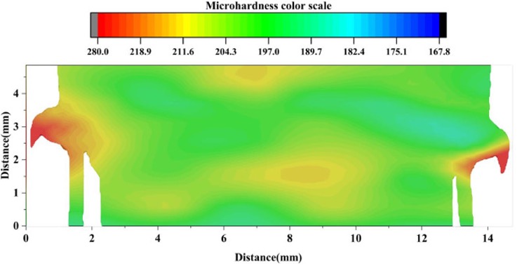
Fig. 13. The micro-hardness profiles in the Vickers-scale across the thickness section of the produced circular weldment showing the indentation resistance of bonded regions from the right- and left-sides, concerning the tube and plug base alloys.
Finite element analysis/simulation (FEA) of stress distribution near peak load
In the case of this FE modelling part, it is worth emphasizing that this simulation is about tensile-shear loading of the produced solid-state weldment and how the weld resist loading up to the fracture happens and how the strain localizes across the weld-line during testing. Hence, this modelling analysis only considers the static loading based on the measured applied peak load that was observed during tensile testing.
In the first simulation, the solid rod portion of the sample was fixed on the flat end. This was to simulate the grips of the tensile tester fixing the specimen in place. The tubular portion of the specimen had a force applied to the exposed flat surface of 10.5 kN. This force acted in the normal direction away from the sample to simulate the tensile tested pulling the specimen apart, as presented in Fig. 14. The mesh was set to the finest setting. The material was set to specifications of Zircaloy-4 provided by Cameco.
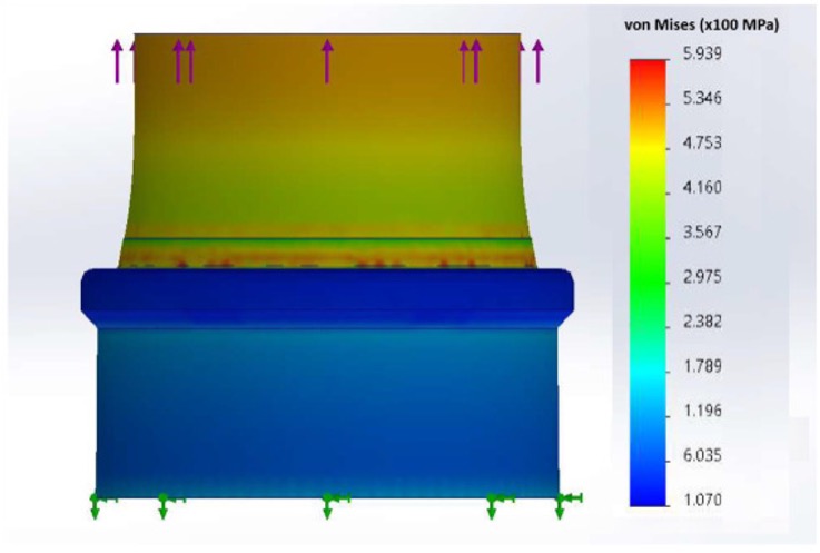
Fig. 14. The FEA simulation results for the overall von-Mises stress distribution after plug to tube Zircaloy joint formation.
Under the specified conditions, the first simulation showed that the maximum stress would occur within the base of the weld joint, as presented in Fig. 15a, which does not align with what was seen in the tensile test. The second test was run identically to the first, with an additional constraint on the necking behavior of the tubular portion, as shown in Fig. 15b. In the sample, there is a “locator” inner solid section feature of the plug which remains at a constant diameter regardless of the tensile forces applied. This guides the tube over the rod during welding and then prevents the tube from necking near the weld joint. This was simulated using a cylindrical constraint on the inside face of the tube, set to a radial displacement of 0 mm. The diameter of the tube could not be reduced in this simulation. Under these constraints, the region of maximum stress moves out of the weld joint and into the tube material.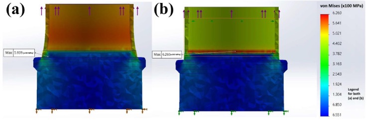
Fig. 15. The cross-sectional von-Mises stress distribution across the circular profile of produced plug to tube weldment for two different loading and constraint states, resulting in the maximum stresses of (a) 593.9 MPa and (b) 626.0 MPa for the most critical regions.
Re-running the study, this time with only half of the height of the interior tube face was fixed, which shows an additional ring of high stress at the boundary between the radially constrained and radially unconstrained portions of the tube, as depicted in Fig. 16a. At positions 2 and 4 in Fig. 16b, the respective surfaces of either stress concentration, the von Mises forces are nearly identical, differing by 10 MPA. Halfway into the wall, at positions 1 and 3 (shown in Fig. 16b), the upper ring has von Mises forces 80 MPa higher than the lower ring. While the lower ring has a slightly higher peak stress value, the upper ring’s stress distribution is much more pronounced within the tube wall. This indicates that the zone highlighted by the upper ring would fail first, which is what is seen in tensile tests.
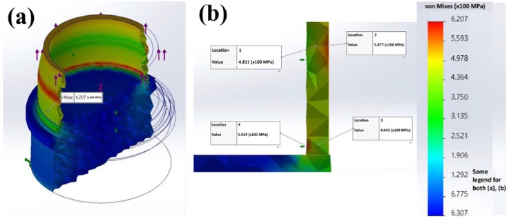
Fig. 16. (a) Thickness cross-section of the circular joint profile demonstrates the distribution of von-Mises stress. (b) The specific von-Mises stress values regarding four different locations across the produced weldment.
All failures occurred in the tube, far away from the base of the joint, in areas that can freely undergo necking and radial deformation. When the tube is not only radially constrained, but also has an unconstrained portion, the unconstrained portion will experience the highest amount of stress. Also, there is a good correlation between the simulation stress peaks and the experimental fracture positions observed in the specimens produced at lower temperatures and exhibiting interfacial fractures, which can be attributed to the high stress zones produced in that location as shown on Fig. 15.
Hence, as the closing statement, this work represents the first case of Zircalloy-4 plug to tube joint design using the innovative IKW technology and to demonstrate fully solid-state joining with an efficiency of 100%, concerning the literature on Zr-joining (Jiang et al., 2024).
Conclusions
The main results regarding the modelling and experimental studies on tube to rod/plug butt-joint design of Zircaloy 4 using the solid-state induction kinetics welding can be summarized as the following.
• Based on the predictions undergoing finite element simulation, frictional deformation bonding caused by in-contact tangential rotation after induction heating up to high-temperatures can result in shifting the maximum stress-state outside of the weld joint area, mainly toward the tube design material.
• The effects of testing temperature in the range of 1000 to 1600°C and tangential rotation angle in the field of 0 to 90-degrees, were found to be crucial processing parameters, based on the quality of metallurgical bonds formation between the Zircaloy 4 tube to plug butt-joint design.
• Induction heating up to a peak temperature of around 1400°C followed by the subsequent friction-bonding with a tangential rotation of up to about 60-degrees resulted in the best solid-state joint formation.
• Microstructural investigations by optical microscopy and EBSD analysis revealed the grain structural characteristics of different regions across the solid-state bond-line formation across the tube/plug cross-section. A very narrow bond-line with the minimized HAZ was formed across the tube/plug joint design. Shear-based rotation across the components induced considerable microstructural refinement in the rotated bond line concerning the zirconium alloy base metal grain structure.
• Uniaxial tensile testing of the joint exhibited fracture from the tube base alloy when a preheating temperature of 1400°C was used, with an average fracture load of 10.8 kN. Such the joining efficiency of up to 100% under the optimized IKW processing parameters exhibited good repeatability of production and excellent performance.
• Indentation micro-hardness mapping approved the perfect quality of solid-state joint formation at the interface, with some level of hardening attributed to tangential friction rotation and upsetting, also yielded the pushing of oxidized regions (with high hardness values) outside of the joint and geometry, that could be straightforwardly machined after the joining process completion.
Direction for future research
As the closing statement, for this case of Zircaloy-4 plug to tube joint design, using innovative IKW technology in this research, we achieved solid-state weldments with the joining efficiency of 100%, which was not possible with the other existing solid-state welding methods. As such, this technology represents a potential method for similar and dissimilar joining of other metals and alloys due to the solid-state bonding that is achieved with minimal flash ejection and brief welding time to produce a full joint.
CRediT authorship contribution statement
Farzad Khodabakhshi: Writing – review & editing, Writing – original draft, Visualization, Validation, Methodology, Investigation, Formal analysis, Data curation, Conceptualization, Project administration.
Mark Turezki: Visualization, Validation, Software, Investigation, Data curation, Methodology.
Adrian P. Gerlich: Writing – review & editing, Supervision, Resources, Project administration, Funding acquisition, Conceptualization.
Declaration of competing interest
The authors declare that they have no known competing financial interests or personal relationships that could have appeared to influence the work reported in this paper.
Acknowledgements
The authors would like to acknowledge the support provided by the Natural Sciences and Engineering Research Council of Canada (NSERC) [grant number ALLRP 586457-23], along with the welding support and financial support of Sorsys Technologies Inc. (Mr. Saman Sahraeinejad), and FuseRing Inc. (Mr. Paul Cheng). EBSD was performed at the Canadian Centre for Electron Microscopy a core research facility at McMaster University (also supported by NSERC and other government agencies).